So what was actually needed to build a battleship? How was a pile of metal turned into a vessel capable of ruling the waves?1
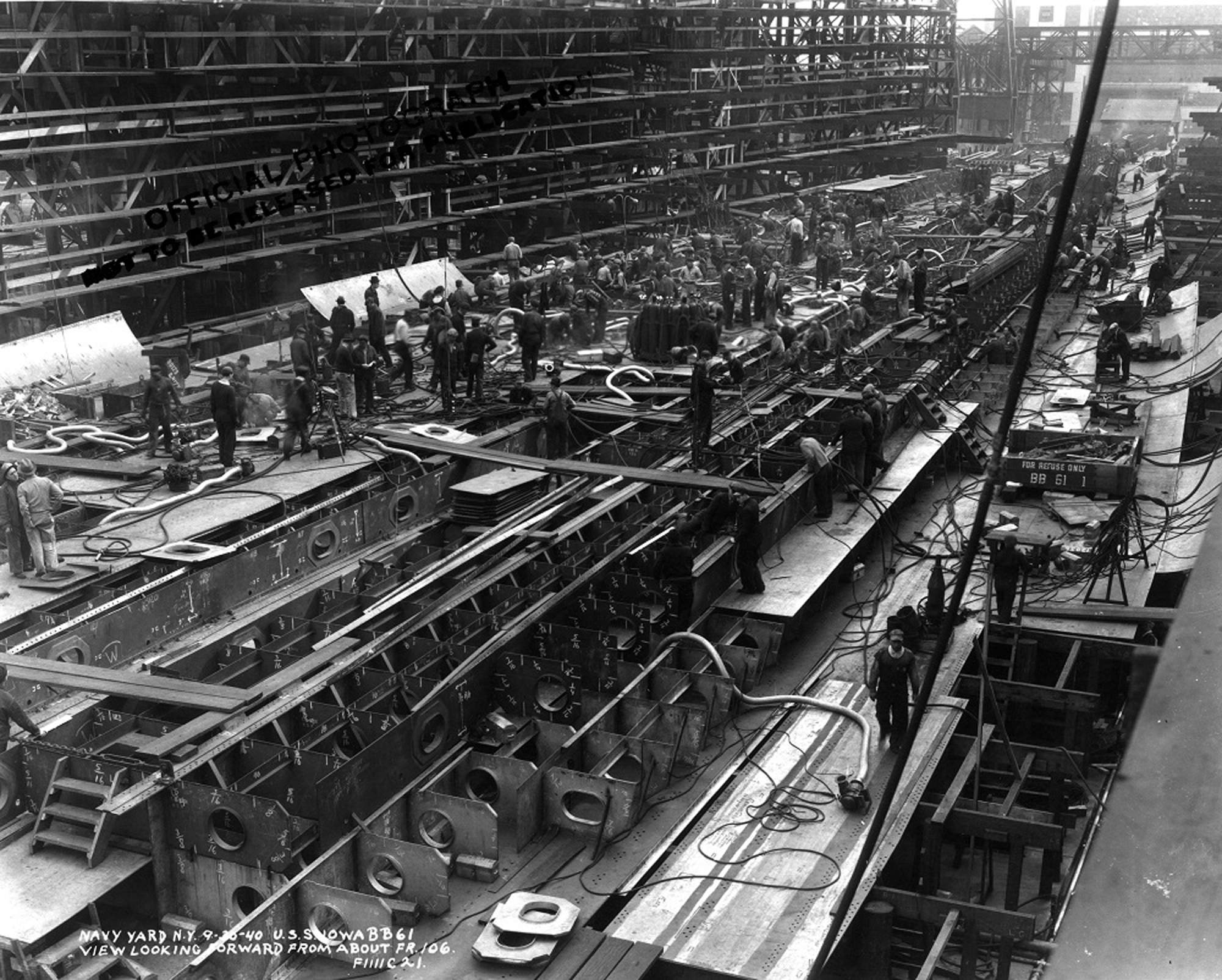
Iowa takes shape on the building slip at Brooklyn Naval Yard
It all started with a piece of land. This land needed to be firm enough to support the vessel as it was being built, and next to a body of water into which the vessel could be safely launched. It also needed good access to the sources of building materials, and to skilled workers. Once the land was secured, a building slip was constructed. This sloped gently towards the water, usually at about 3°, to make it possible to launch the ship when it came time for that. The ways, the main supports for the ship under construction and the rails which she would slide down at launch, were then laid. These were built primarily of timber, and for a battleship were approximately 8' wide and 30' apart. In the center, a line of wooden building blocks was placed to provide the primary support for the vessel as it was assembled. These allowed men to work underneath the ship, and provided clearance for the launching cradle when it was installed.
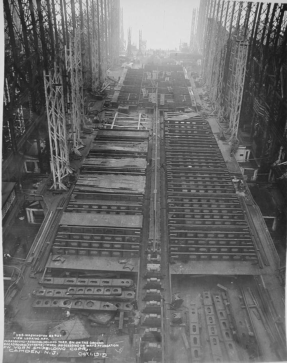
The building slip for USS Washington (BB-47). The keel blocks are visible towards the bottom of the photo, while the ways are under construction towards the top.
The next task was producing the various pieces of metal that make up the basic fabric of the ship. Raw material was bought from commercial sources and formed into the necessary shapes on-site. The yard would prepare working drawings from the master plans supplied by the navy, and these would then be converted into full-scale wooden templates in the mould loft. The mould loft was a large, well-lit area, usually above a workshop, where skilled men filled in the gaps in the drawings and produced templates for the plates and frames. Plates were cut to shape with giant shears, rivet holes were punched or drilled,2 and rollers were used to bend the plate to the correct shape. The much stiffer frames were bent hot, using hammers, presses, and metal templates based on the wooden ones produced in the mould loft. Specialized pieces like shaft brackets and the stem (bow) and stern castings were cast or forged to their final shape by outside specialists and shipped in.

The Mould Loft at John Brown's Clydebank shipyard, 1901
The metal pieces would then be taken out to the slip, where they would be fitted into the growing hull. They were hoisted into place by a light derrick or crane, usually with a capacity of no more than 3-5 tons, and temporarily bolted into place.3 A riveting gang would then arrive to fasten them permanently to the ship's structure.4 Each rivet would be heated in a nearby furnace by the rivet boy, then passed to the catcher, who would place it in the hole. A holder-up would then hold the head of the rivet against the riveter(s), who would buck the tail of the rivet to hold the plates together. Through about 1910, rivets were bucked by a team of men, usually two, armed with hammers. Later on, a single man armed with a pneumatic riveter was used instead.

A man uses a pneumatic riveter, c.WWI
There were several drawbacks to riveting. Besides being labor-intensive, it tended to produce heavy structures. To provide enough space for the rivets, plates had to be overlapped or strapped, and stiffeners had to have extra flanges for attachment. The lines of holes also weakened the plates, the usual assumption being that this cost 1/7th of the plate's normal strength. More than that, riveted joints were not inherently watertight. Any watertight joints had to be caulked, with the edges of the plate split, and one side forced down into the other plate. Joints that had to be oiltight, such as fuel tanks, had to be caulked even more carefully, and welding was enthusiastically adopted for these areas.
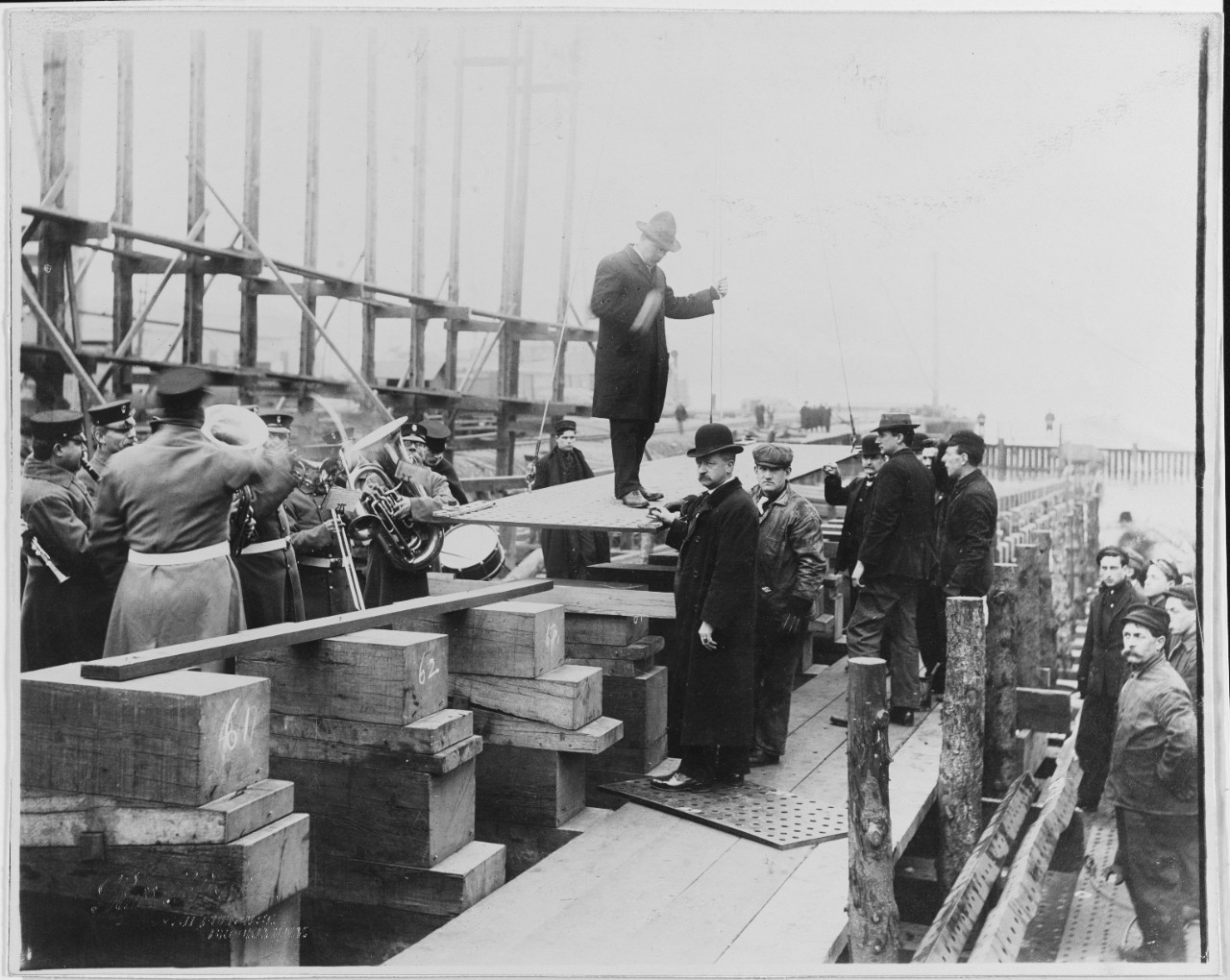
Laying the keel of USS Florida, March 8th, 1909
Actual assembly began with the keel, the structural backbone of the ship. Its laying was usually the subject of some ceremony, as the official start of the ship's construction. After that, the double bottom with its frames, longitudinals, and inner and outer bottom plates was assembled. The frames that defined the ship's sides followed, along with the side framing and plating. Throughout assembly of the ship's structure, great care was taken to make sure that it matched the designed shape. Once enough structure was in place, to make sure it wouldn't shift, important structures like machinery mounts and shaft brackets were installed and aligned. These, and other heavy fittings like the stem and stern castings and transverse armored bulkheads, were usually erected using temporary wooden shearlegs, as the permanent derricks lacked the capacity for them.
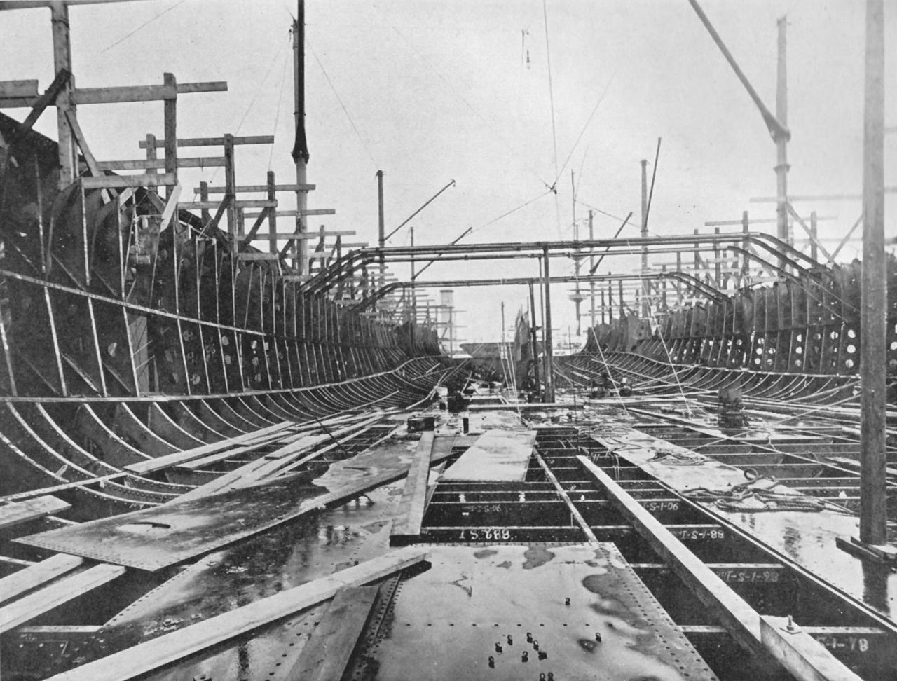
HMS Dreadnought's frames show in this view two days after her official keel-laying5
For most battleships, the next step was to install the strength deck in preparation for launch. At this point, there would be several obvious components still missing, most notably belt armor, machinery and turrets. There were several reasons for this. First, this made the ship lighter at launch, which reduced stress on the ways and made the hull easier to control. Second, these components were heavy and would have required much more powerful lifting apparatus than was traditionally installed on the slipways. By waiting until the ship was afloat,6 the builder could make more efficient use of the expensive heavy cranes. This changed towards the end of the battleship era. Internal belts had to be installed before launch, and better cranes made it practical to add machinery and fully seal the hull before launch, instead of just bolting on some of the upper deck for later access.
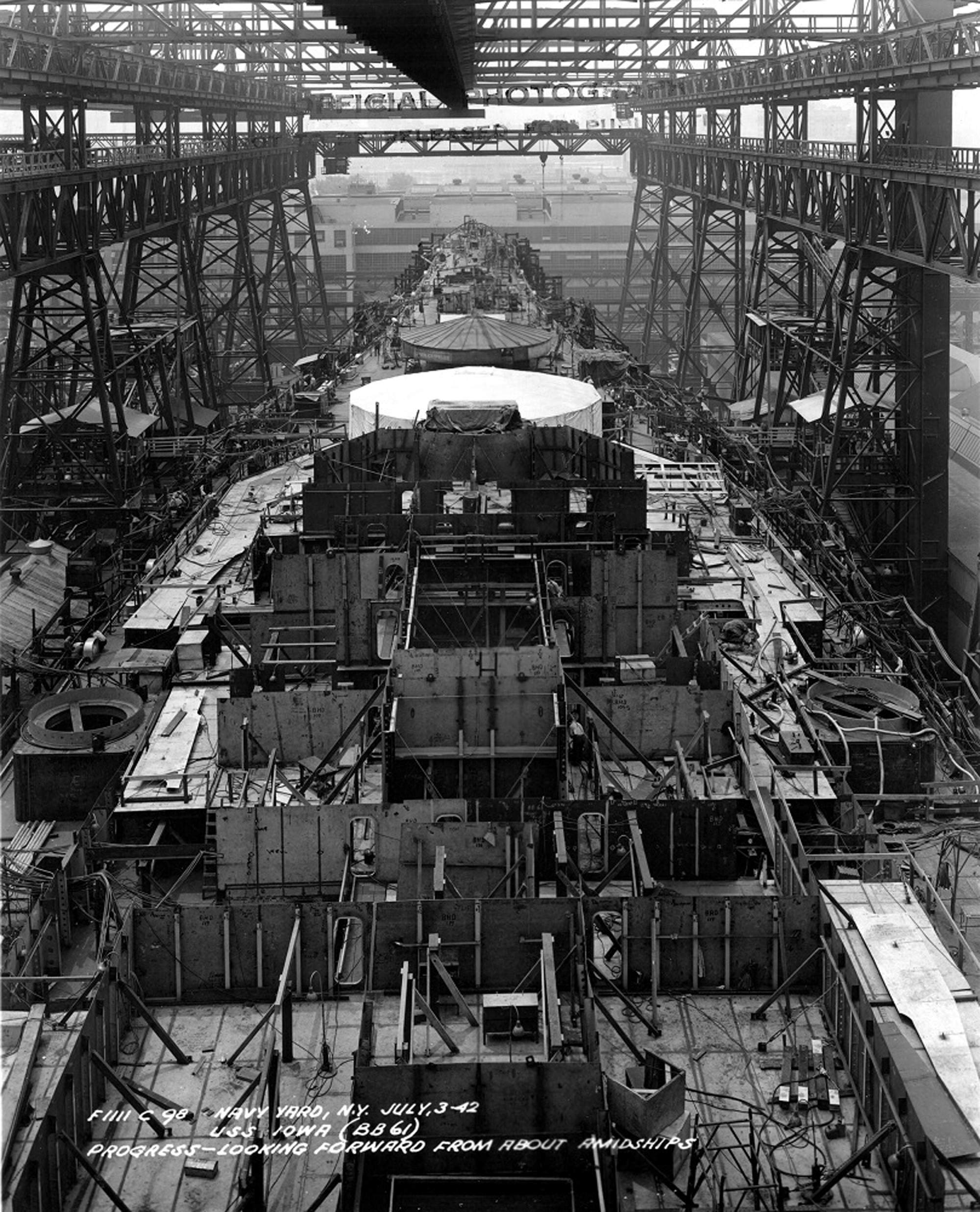
Iowa two months before launch
But ultimately, the day would come when it was time to send the hull sliding down the ways and into the water for the first time. I'll discuss that process, and what followed it, next time.
1 Two notes on the following. First, I'm describing practice during the battleship era, and modern shipbuilding techniques are very different. Second, this is based almost entirely on British practice, due to the limitations of my sources when I wrote it, although American practices were broadly similar. I've since gotten more information on WWII USN methods, but will probably put that in a separate post. ⇑
2 Punching was much more efficient, but it cold-worked the holes, making them more likely to crack. Drilling was used on critical holes in the structure instead. Where accuracy was critical, practice was to punch undersized holes, then clamp the pieces together on the slipway and drill the holes to final size. ⇑
3 This is where modern practice differs most radically from that of the battleship era. Today, most ships are constructed using modules. Large blocks are assembled elsewhere in the shipyard, including things like cables and piping, and only then assembled. These modules can be up to 1,000 tons, as on the new Ford class carriers. Towards the end of the battleship era, heavier cranes were often used, which allowed more assembly to be done in shops instead of on the slipway. ⇑
4 Structurally, all battleships were riveted. Even the Iowas, which were extensively welded topside, had most of their structural elements riveted. Illinois and Kentucky would have had much more extensive welding, but neither was completed. ⇑
5 Fisher essentially cheated to get Dreadnought credited with a very quick building time. A lot more work was done than normal before the keel was formally laid. ⇑
6 The contracts the Admiralty issued to commercial builders specified that the ship had to remain afloat at all times while being fitted out. ⇑

Comments
I assume that if one of us wanted to build a battleship today, we'd be doing it in a drydock rather than on a slipway, and that we'd be welding rather than riveting almost everything. Do you know how close shipbuilders were to being able to do that back when battleship construction was still a thing? The Panzerschiffen were famously welded (or at least mostly-welded), but it's blasphemy to call those battleships, and presumably the welding technology of the day didn't scale to e.g. battleship-thickness armor plate. And while there were a few dry docks capable of holding WW2-era battleships for repair, I don't recall any being used for construction.
Face-hardened armor can't be welded, period. It would mess up the heat treatment. Homogeneous armor is weldable, and Iowa's conning tower is in fact welded, despite being 17.3" thick.
And as far as I know, every battleship was built on ways and launched conventionally, not in a drydock. But that's not how we'd do it today, because things there have changed a lot.
I'd never really thought about it before, but now that you mention it it does seem very odd to me that even the late battleships were never welded. Why not, given how many cruisers were?
Strictly speaking, I would think you'd be able to weld face hardened plates as long as your welding heat affected zone (HAZ) stays within the annealed portions of the plate. Since the rule of thumb I've always worked with (admittedly mostly for aluminums) is that 1-2x the width of your weld bead constitutes the HAZ, and as memory serves the face hardened portion of the armor is only the top 6" or so of the plate, so you could stitch the plates together from the internal faces and to the stringers/frames. Of course that leaves aside interesting materials tricks we learned since then, and I'd think you'd be looking at some sort of trick like explosive welding to create metallic composites for your armor, if not go whole hog into an advanced composites design. Then you could do all kinds of interesting things with variable densities and use plate stock thin enough to cold work in useful ways.
@cassander
I'd suspect it was conservatism. Battleships are very expensive, and you're not going to get many chances at them, so if you screw them up, it's a really big deal. I can't find details without the relevant Friedman, but the USN doesn't seem to have introduced structural welding until ~1935 in cruisers, with the ships actually entering service a couple years later. The earliest I can actually confirm the use of welded structure in cruisers is on the Brooklyn class, and I don't think they were all-welded. And I suspect that the structural benefits of welding were largest on light, highly-stressed destroyers, too.
@ryan
I'd still be nervous about the welding messing with the metallurgical properties of the back of the plate, which is just as important as the front in terms of keeping shells out. But it's been a long time since I learned about welding and I still don't have a great grasp of armor metallurgy (or metallurgy in general). Which is why I'm not really qualified to comment on what battleship armor would look like if we were to try to make some today. It's certainly possible that some form of fun composite armor could be made to work (similar techniques were used in the 1870s and 1880s), but I don't know enough about state-of-the-art techniques to be able to say more.
@bean
I imagine that if we were looking at modern battleships, modern tank armor would be a pretty good first approximation. Though these days that does conjure the....Interesting image of a battleship with an active protection system.
Looking into this, the U.S. Army Ordnance Department claims to have to adequately weld a tank turret's worth of face-hardened armor in 1938 and two complete M-3 medium tanks in 1941, but found the process too troublesome for mass-production. They did publish the process for use in field repairs, at least. And I'm seeing claims that this was based on a Swedish process from 1934, but I haven't been able to confirm that.
Source: The Ordnance Department: procurement and supply, Volume 2; Volume 6, page 248, per Google Books
So, doable but not practical on a battleship scale in the battleship era.
I don't think you'd want to use tank armor as your model for a modern battleship, as that's meant for a different problem. Antitank weapons are optimized to produce very deep, very narrow holes because tanks are sufficiently compact and densely packed that any penetration is likely to be a mission-kill. It probably isn't possible to armor a large ship well enough to prevent an ASM-sized shaped charge or long-rod penetrator from getting through, but small holes won't reliably mission-kill large ships so the enemy will probably be trying to push a substantial explosive warhead through whatever armor you have in place.
On the other point, IJN "Yamato" appears to have been constructed in a dry dock at Kure, while her sister "Musashi" was laid down on a conventional slipway at Nagasaki. "Musashi" also had an unexpectedly exciting launch, and "Shinano" went back to a dry dock, suggesting that 60,000 tons may be about the limit for conventional construction techniques.
An active protection system for a battleship is called a CIWS, which have been used to shoot down rockets before, and could probably deal with shells, too. As John points out, the threat environment for a battleship is rather different because the ship is large and durable, and not going to be killed with a single small-caliber hit.
@John
AIUI, face-hardened tank armor of the day was essentially harveyized, with a very thin, very hard face to break shells. That process doesn't rely on heat treatment in the same way that battleship armor does, and would presumably be a lot easier to weld. Also, an M3 has at most 2" of armor, which is a very different matter than trying to weld a 12" belt. I remember that much from my manufacturing course.
And good catch on Yamato. I may see if any of my sources have interesting things to say about Musashi's launch.
As an engineering undergraduate we had a case study on all-welded ships. They introduced failure modes that riveting avoids. Particularly, if a crack starts in one plate it can grow and grow. If the crack meets a riveted joint it stops there because the next plate is a different bit of metal. But if the plates are welded together the crack can keep going and there is nothing to stop it until the ship cracks in half. (Note that the larger the crack, the more it will grow and the growth speed accelerates until it reaches the speed of sound at the worst case.)
This is not a theoretical risk. The USA had a bunch of welded ships in WWII and it was a known problem that sometimes they just cracked in half. Often in a heavy sea in the mid ocean. At the time this was a known risk but the enormous increase in production speed/lower cost was judged to be worth it. (Given that there was a war on.) Not for capital ships however.
After the war welding was abandoned for a few years while engineers were able to sit down and work through the problems methodically.
That’s not the whole story. The only warship I’m aware of to lose a major section of structure without taking battle damage is Pittsburgh, and that was due entirely to poor welding. I wouldn’t swear that there were no destroyers lost to similar causes, but Sumrall doesn’t seem to mention welding in his book on the Sumner/Gearings, which made up a lot of the welded destroyers. (I don’t have similar sources on the Fletchers, the other class likely to be affected by wartime practices.)
Most of the failures were a combination of welding being worse at stopping crack propagation than riveting with poor grades of steel that lost ductility when they got cold. The most notable incident was the T2 tanker Schenectady, which broke in half in a still harbor. I do not believe this steel was used in warships.
I’m skeptical of this, because the advantages of welding are significant. It’s possible that it occurred in merchant construction, but I don’t think it was the case for warships. DK Brown states in Rebuilding the Royal Navy that riveted “crack arrestors” were used, usually at the upper deck edge and the turn of the bilge, until improved steel and techniques alleviated the problem. These are much more plausible, as they preserve almost all of the advantages of welding while fixing the cracking problem. He also gives an account of the carrier Vengeance, which suffered a crack running across the flight deck and down both sides during an arctic exercise.
I also remember reading somewhere of cracks propagating through riveted joints, although I’m not sure where, and it was definitely rarer. Let me do some more reading on this.
(Just to be clear, I do intend to do a full post on the introduction of welding at some point. It’s just going to be a while.)
Edit: I checked Practical Construction of Warships (1955), and there were a couple of problems. Welding can make steel, particularly low-quality or armor steel (these are separate things, to be clear) significantly more likely to crack than it would be if it was riveted, particularly if the construction technique used is bad or the welds are low-quality. The Victory Ships, which used the same steel but better design, didn't have the same problems.
This is probably a silly question, but did the tools used for building the ship on the slip take into account the slope? I.e. Did the levels and things all have a 3 degree offset, or did they account for it some other way?
Sort of. You'd probably use shims instead, because you might, for instance, be working across the ship where there is no slope. But it was a definite problem. I just finished a book on building a DDG on ways, and that was mentioned as one minor reason they really prefer to work on the modules in the shop rather than doing work on the ways.
I followed up to the wiki article on the SS Schenectady, and it sez: "She was repaired and successfully entered service in April 1943"
After cracking almost entirely in two! I can't imagine she was a popular ship to serve on after that, though.
Says something about the voracious hunger for merchant vessels the Allies had, and maybe something about the prowess of Allied shipyards in repairing terrific damage in WWII.
A lot of ways, that was an easy repair. It just broke pretty cleanly in half in a calm harbor. Yes, the ship being in two parts looks really bad, but you really just need to weld it up and fix any piping or wiring that got torn in the process. This is a lot easier than many repairs they made. If something similar happened today, the insurers would almost certainly have it fixed.
I guess so, especially if the machinery spaces didn't get flooded. It's not exactly the Mary Ellen Carter...
(Where the supposed value of the ship probably wouldn't have covered the cost of salvage if it hadn't been done "for free"
Which reminds me, after they salvaged it, who would own the ship? I assume the insurance company, who would owe the salvage crew a salvage fee?)
Salvage definitely isn't "finders, keepers". Whoever owned it previously gets to keep it, and they have to pay a fee to the salvor. If it's not agreed on beforehand, then it goes to an Admiralty Court. Standard procedure these days (going mainly off of documentaries I've seen) seems to be for the insurers to get a contract with the salvage firm before work starts. I suspect those are standardized to make it easy to ring a salvor and say "we've got a ship on fire and need you to fix it". Although if a salvage ship is on-hand, they'll chip in and figure it out later.
The standardized contract is called the ["Lloyd's Open Form"] (https://en.wikipedia.org/wiki/Lloyd%27sOpenForm). The following videos from a salvage company discuss signing the contract before they start work. I've cued up the video to the applicable portion, but they're worth watching in full if you're interested in marine salvage: https://youtu.be/rfkJ1Q7cglE?t=94 https://youtu.be/PTPeUXpOMh0?t=169
Note that the Lloyd's Open Form is marked "No Cure, No Pay" because if the salvor doesn't succeed, they get nothing, and AIUI, if they do succeed an arbitrator will determine the payment after the fact.
OK, so apparently I can't figure out this stupid Markdown for links. I don't know why they manage to make it harder than just using the stupid HTML https://en.wikipedia.org/wiki/Lloyd%27s_Open_Form https://youtu.be/rfkJ1Q7cglE?t=94 https://youtu.be/PTPeUXpOMh0?t=169
I think that should do it?