Strength is one of the main concerns of the naval architect. Supporting the loads of the ship while it moves across the sea, and while the sea moves around it, is not a trivial problem. The structure also needs to be as light as possible, watertight, and cheap to build.
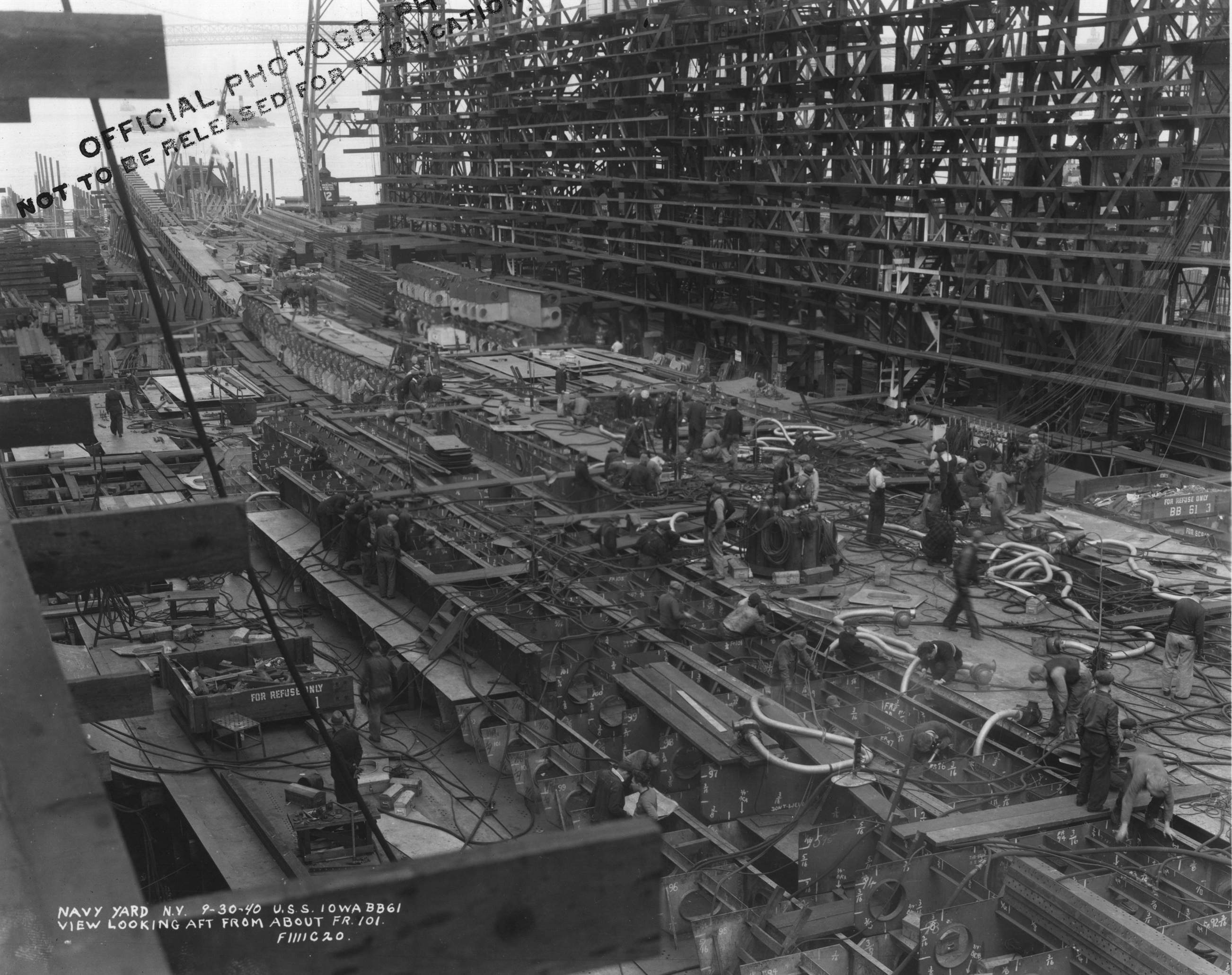
Iowa's structure being assembled at Brooklyn Navy Yard
The most serious loads on a ship come from the uneven distribution of weight and buoyancy. While the total weight and buoyancy will be equal when the ship is at equilibrium,1 it is common to have weights in the ends of the ship that overwhelm the buoyancy provided by the fine lines there, and are supported from the broad center section.
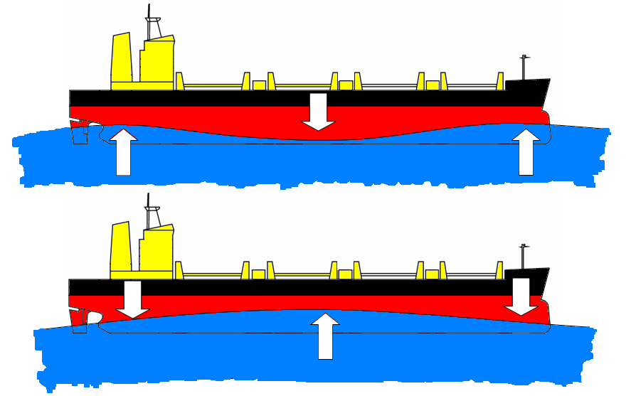
Sagging (top) and Hogging
However, ships do not always rest on flat water, and ship structure is usually sized by stresses caused when waves change the buoyancy distribution. In the age before computers two worst-case scenarios were usually calculated, known as hogging and sagging. These occur when the length of the local waves is the same as the length of the ship. Hogging happens when the crest of the wave is in the center of the ship, leaving the ends in the middle of the trough, while sagging is when the crests are at the ends and the middle is undersupported. To a first approximation, the ship can be analyzed as a beam, with the uppermost continuous deck and bottom plating of the ship being the upper and lower flanges and carrying the most stress. When the ship is hogging, the upper deck is in tension and the bottom in compression, while in sagging, the forces are reversed. Traditionally, a wave height equal to 5% of the wave's length was used, but modern practice is to use a constant wave height of 8 m.
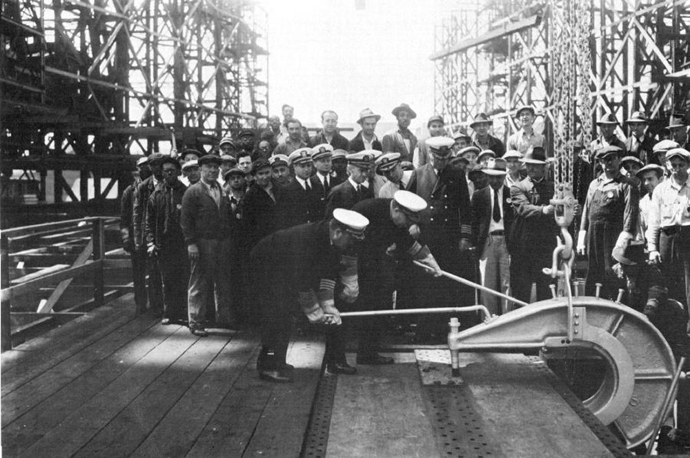
Iowa's keel being laid by Admiral C. H. Woodward, Chief of the Bureau of Construction and Repair
A ship's structure starts with the keel. In steel shipbuilding, the keel is the structural backbone of the ship, located on the centerline at the lowest point of the ship. Unlike the hydrodynamic keel of a sailboat, the keel we're discussing does not protrude out below the bottom of the ship. It's an I-beam structure, built up by welding or riveting plates together. A ship's construction is usually considered to begin when the first two pieces of the bottom plate, known as the keel flange, are fastened together. The keel laying is usually ranked alongside launching and commissioning as the most significant milestones in a ship's life before she enters service. The height of the keel structure can vary from two feet in smaller ships to as much as 7' in the largest vessels.
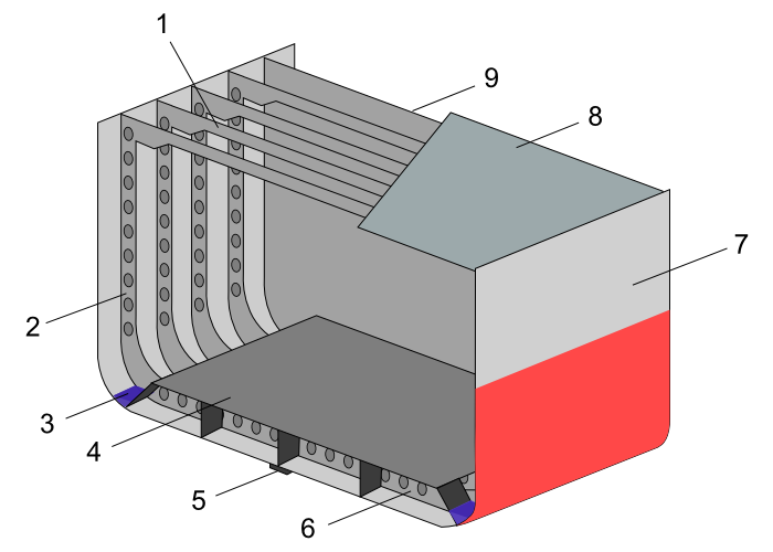
A transversely-framed ship. 1. Beam 2. Frame 3. Bilge 4. Inner Bottom 5. Keel 6. Outer bottom 7. Shell plating 8. Deck plating 9. Bulkhead
If the keel is the backbone of a ship, the frames are the ribs. In the traditional transversely-framed ship, there are many closely-spaced frames placed at right angles to the keel that define the shape of the ship. Transverse beams close the top of the frames and support the decks. These are easy to build in wood or using rivets, but the frames contribute nothing to resisting hogging or sagging, so ships designed with this method tend to be heavy. The alternative, introduced to warships during the 1930s, is longitudinal framing. This has many longitudinals running parallel to the keel to define the ship's shape and contributing to its main strength, with widely-spaced transverse frames intended only to give sufficient torsional strength. Particularly when welded construction is employed, this approach can be much lighter than transverse framing. However, transverse framing is often used towards the end of the ship. Longitudinal strength is less important there, but the need to resist crushing forces, such as might happen in a docking accident, means that transverse strength is vital.
Frames are also the standard longitudinal markers within a ship. Iowa, for instance, has about 216 frames, each 4' apart, and compartments are designated partially by their forward frame. Some of these frames are extended to form watertight bulkheads, which play a vital role in combating flooding and also increase the ship's transverse strength even more than the frames do. There are also longitudinal bulkheads fitted to many ships. While centerline bulkheads tend to cause ships to capsize in the event of underwater damage, longitudinal bulkheads also formed the basis of torpedo defense systems.
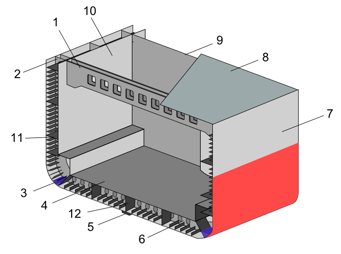
A longitudinally-framed ship. 1. Beam 2. Frame 3. Bilge 4. Inner bottom 5. Keel 6. Outer bottom 7. Shell plating 8. Deck 9. Bulkhead 10. Inner hull plating 11. Stringer 12. Keel vertical plate
Covering all of this was the outer skin, known as shell plating. Shell plating's main purpose is to keep the water out and the air in, but it also contributes meaningfully to structural strength. How much depends on the design approach. Warships of the early Cold War tended to have thin skin with heavy framing to resist the shock of a nearby nuclear detonation, which tended to produce a phenomenon known as "hungry horse" as the skin stretched over the frames. Modern ships are more likely to use thick skin and light framing. Plating is usually arranged into strakes, rows the length of the ship much like the planking on wooden hulls. On welded ships, these are butted together and welded flush, but on riveted ships, they often overlap. The strakes immediately adjacent to the keel are known as the garboard strakes, while the uppermost continuous strake is the sheer strake. Both of these are structurally important and are usually thicker than other strakes. In many ships, a double bottom the height of the keel is formed when a second set of watertight plating is placed on top of the frames. Cells in the double bottom, defined by the frames and longitudinals, can be used to store liquids, and it provides protection from damage to the bottom. In some ships, the double bottom runs all the way up to the sides, although in most vessels the inner bottom stops well short of the upper deck.
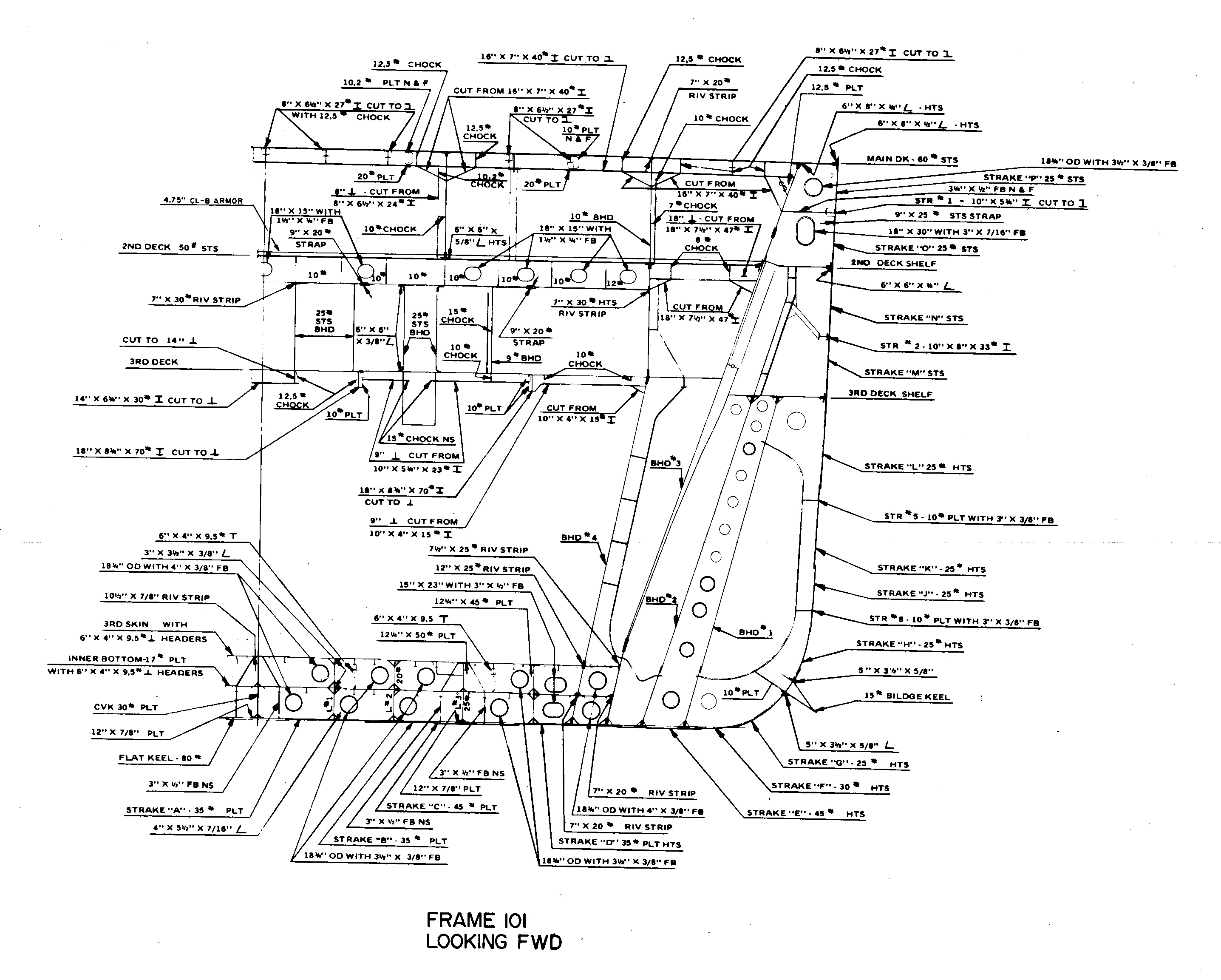
A cross-section of Iowa's hull at Frame 101
The uppermost continuous deck is known as the strength deck, and it's usually the highest deck that runs across the ship from side to side and from bow to stern. Anything above this is known as the superstructure, and is not usually designed to be watertight or load-bearing, although there are some exceptions. US aircraft carriers before the Forrestal class were designed so that the hangar deck was the strength deck, and everything above it was superstructure. This was necessary because the US wanted an open hangar, which meant that planes could be warmed up inside, and lifts could be installed in the edge of the deck. Modern carriers have the flight deck as the strength deck, but clever design allows deck-edge lifts, and jets take far less warming up than piston engines do. Ships fitted with forecastles to improve seakeeping had to step the strength deck down at the break of the forecastle, which had a tendency to produce stress concentrations. Any design mistakes in this area can lead to cracking, or even the ship breaking in half if subject to an underwater explosion. The designer generally wanted to keep the strength deck as high as possible, as this allowed him to reduce stress and use less material. In a few cases, ships were even deliberately made taller to make their hulls lighter. The deck is usually built so it is slightly higher in the center to allow water to run off, and with the outermost (stringer) strakes at the edges thicker than the others, as those bear the most stress.
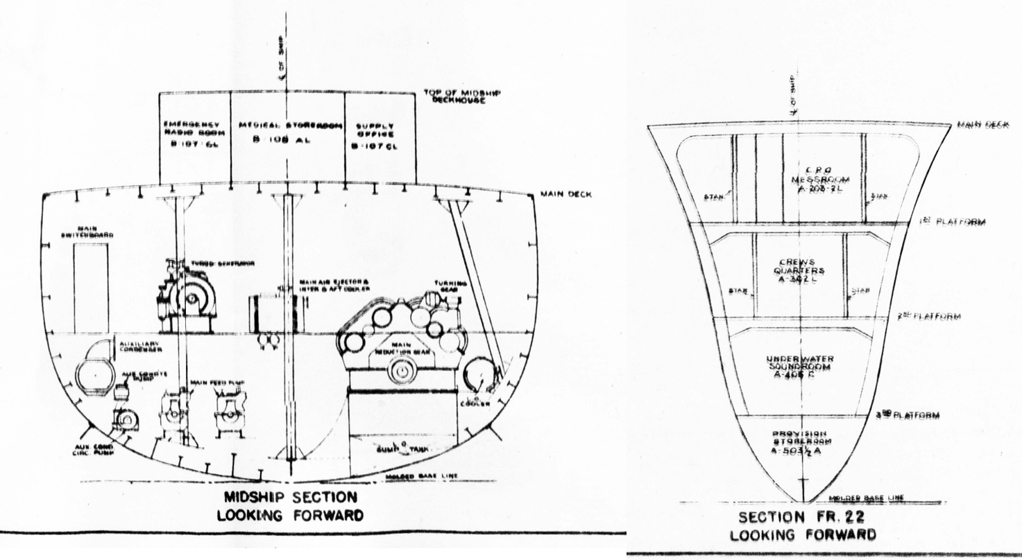
Sections of a Fletcher class destroyer, showing longitudinal framing amidships (left) and transverse framing forward (right)
Besides the broad outlines I've laid out here, there are lots of details that have to be taken care of to build a practical ship's structure. Any opening in a deck, bulkhead, or other structural member will require extra structure to compensate for the resulting weakness. Concentrated loads, like barbettes and machinery, need to be dispersed across the ship, and special foundations are required to make this happen. And all of these members have to be fabricated and then fastened together. How that happened, particularly in the battleships, is our story for next time.
1 If weight is greater than buoyancy, the ship isn't in equilibrium and will sink deeper into the water. This could end up with the ship being underwater, in which case it's not really a ship any more. If buoyancy is greater than weight, the ship will rise higher. This state must reach equilibrium, unless the ship is actually a blimp, and in that case, it really shouldn't have been in the water in the first place. ⇑

Comments
I feel you should get in touch with Randall Munroe of xkcd, the results of which could be sheer awesomeness of dry wit and tangential surrealist lunacy.
I suspect he's really busy, and our domains don't overlap too much, either. But I'll take that as a compliment anyway, as I do really enjoy his stuff.
Bean, is there a way to make your images zoom in, or at least scale to the window size? Looks like you're using a fixed width and those cutaways of the frame are impossible to read on my browser (tried a couple different ones).
Just click on the image. Those were extracted from the collections of general plans from hnsa.org.
It works on desktop Firefox, but not Internet Explorer or mobile Safari. Haven't had a chance to try it on Chrome.
I just tried it on IE, and it didn't work there, either. I have no clue what's going on, but I'll ping Said Achmiz.
@gbdub:
Image zooming should now work on Internet Explorer 11. (I’m afraid I don’t have earlier versions of IE to test.)
A general note about Internet Explorer support: IE is a very, very outdated browser. It has been discontinued for 4 years (and even before that, lagged far behind other browsers in support for modern web standards). Increasingly, things that work in all other browsers, simply do not work in IE.
In lucky cases (such as this one), a developer may be able to modify a feature to support IE. (This particular modification took almost two hours of work—mostly because IE’s developer tools are very unwieldy.) In less lucky cases, no reasonable amount of effort will suffice to provide IE compatibility.
If you use Internet Explorer, I strongly recommend switching to another browser. If you are unable to switch (because you’re using a computer maintained by your employer, or some such situation), then I regret to say that, while I will make reasonable attempts to provide support (or, at least, to recommend workarounds), it is likely that there are, and will be, features of this site that will not work for you, and it will not be feasible for me to rectify that. (By all means, please continue to report any problems you have—bug reports, or any other feedback, are always welcome! Just be aware that my response may often be “I’m sorry, but this is an IE-specific issue, and fixing it is beyond the scope of what I can do.”)
As far as the mobile Safari problem goes—it may be caused by running an outdated version of Safari (perhaps on an older model of iPhone?). If so, then my fix for the IE problem may have solved the issue in mobile Safari as well. Please try it again, and let me know if it works. If the problem persists, then I’ll need to know your exact Safari version, your iOS version, and your iPhone model, in order to troubleshoot further.
Thank you for fixing that.
@bean:
You’re quite welcome.
@everyone:
By the way, in case anyone wasn’t aware: once you’ve clicked an image to bring up the zoomed view, you can zoom in further by using the mouse wheel (or trackpad scroll, etc.); and then you can drag around to pan the image. (Hit the Escape key to close the zoomed view.) This may be useful for, e.g., some of the diagrams in this post…